Wotian shares the correct calibration method and wiring problems of the pressure transmitter!
From: Issued date 2020.02.19 Back
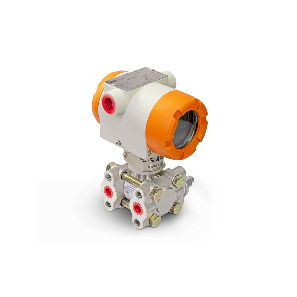
Today, the editor of Wotian mainly came to share with you the correct calibration method and wiring problems of the pressure transmitter.
Calibration of conventional differential pressure transmitters
First adjust the damping to zero, first adjust the zero point, and then add the full-scale pressure to adjust the full scale to make the output 20mA. The on-site adjustment is fast. Here we introduce the quick adjustment method of zero and range. There is no effect on the full scale when adjusting the zero point, but it has an effect on the zero point when adjusting the full scale. Without migration, the effect is about 1/5 of the range adjustment, that is, the range is adjusted upward by 1 mA, and the zero point will move upward by about 0.2 mA. vice versa.
Calibration of Smart Differential Pressure Transmitters
It is not possible to calibrate the smart transmitter with the conventional method described above, because this is determined by the structure principle of the HART transmitter. Because the smart transmitter is in the input pressure source and generated.
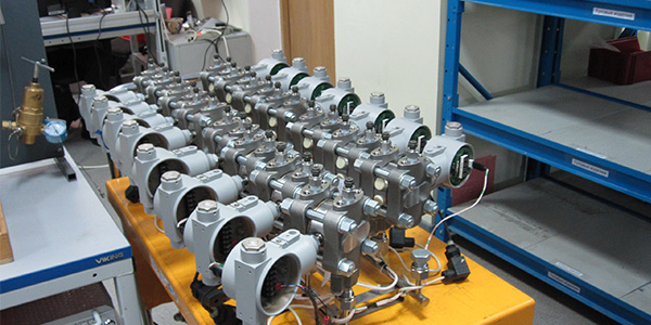
Between the 4-20mA current signal, in addition to the mechanical and electrical circuits, there are also microcomputer chips that perform calculations on the input data. Therefore, calibration is different from conventional methods.
1. First do a 4-20mA trim to calibrate the D / A converter inside the transmitter. Since it does not involve sensing components, no external pressure signal source is required.
2. Do another full fine-tuning to make the 4-20mA, digital reading match the actual pressure signal applied, so a pressure signal source is needed.
3. Finally, do the re-ranging and adjust the analog output 4-20mA to match the external pressure signal source. Its role is exactly the same as that of the zero (Z) and range (R) switches on the transmitter case. :
Some people think that as long as a HART communicator is used, the range of the smart transmitter can be changed, and the zero point and range can be adjusted without inputting a pressure source. However, this method can only be called "setting the range" . True calibration requires a standard pressure source input to the transmitter. Because the range is not calibrated without using a standard, ignoring the input part (input transmitter pressure) to perform output adjustment (transmitter's conversion circuit) is not a correct calibration. Furthermore, the relationship between the pressure and differential pressure detection components, the A / D conversion circuit, and the current output is not equal. The purpose of calibration is to find the changing relationship between the three. Emphasize one point: Only when the input and output (input transmitter pressure, A / D conversion circuit, loop current output circuit) are debugged together, can it be called a true calibration.
At present, the commonly used pressure transmitters are two-wire, with a power isolator, and the output is 4-20mA signal. The transmitter has two input terminals, one for the given signal and the other for the pressure feedback signal. Then the correct installation method is: the signal that the pressure transmitter generally outputs is current 4-20MA, 0-20MA, or voltage 0-5V, 1-5V, 0-10V, etc., usually the current type is two-wire or four-wire system , Three-wire output of voltage. Most of them are 10V, and some transmitters with large power consumption cannot be driven by 10VDC power, so only external power supply 24VDC can be used. In this way, the transmitter has four terminals: power supply +, power supply-, feedback + and feedback-. Current type four-wire system wiring mode: power supply + == power supply +; power supply-== power supply; Current type two-wire connection ratio method: power supply + == power supply +; signal + == feedback +, power supply-,-, if remote transmission is needed, a loop is required, such as 24V + connected to pressure gauge +, pressure gauge- connected to 4-20mA + 4 ~ 20mA- can be connected to 24V-, there may be a terminal in the middle, look at the circuit diagram.
Voltage type three-wire system wiring mode: power supply + == power supply +; power supply-(signal-) = = power supply-; signal + = = feedback +, power supply-(signal-).

