What are the wiring methods of PT100 temperature sensor?
From: Issued date 2021.03.25 Back
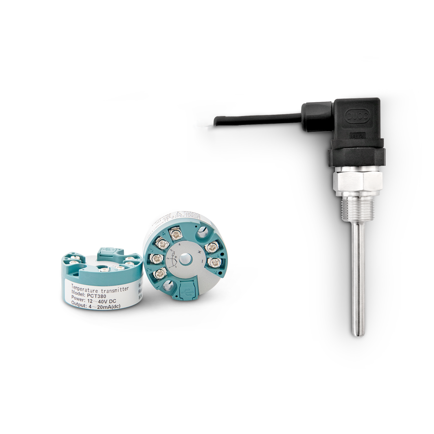
About the PT100 temperature sensor is directly installed in the Pt100 platinum resistance junction box (the thermal resistance integrated temperature sensor is composed of platinum resistance with different structures), and the thermal resistance Pt100 resistance signal is converted into a two-wire output. The following editor tells you what are the wiring methods of the PT100 temperature sensor?
Using Pt100 temperature sensor for long-distance transmission of Pt100 platinum resistance signal, there is a strong on-site interference source, or the signal needs to be connected to the DCS system. The platinum resistance temperature sensor adopts a unique double-layer circuit board structure, the lower layer is the signal conditioning circuit, and the upper layer is the circuit that determines the sensor type and measurement range.
Features of Pt100 temperature sensor.
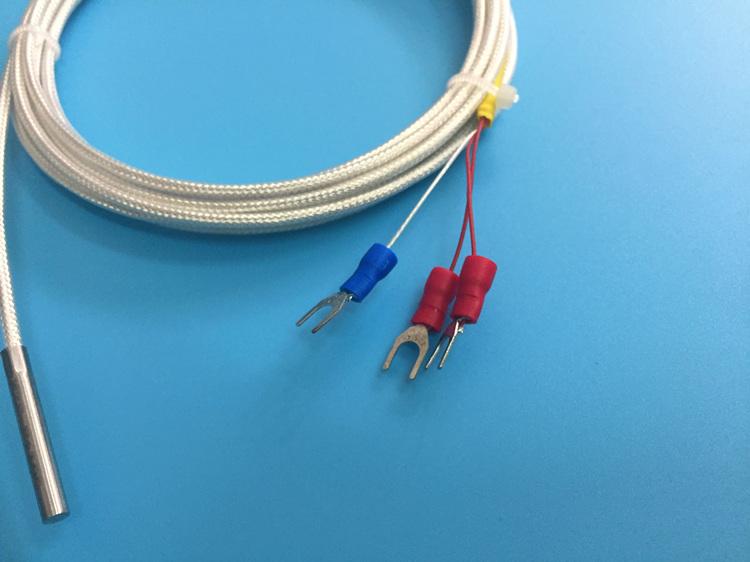
Linearized output 2-wire 4-20 mA standard current signal, adopting modular structure.
Thermal resistance temperature sensor is an assembly of imported British thermometer sensor parts, keeping the original temperature sensor circuit, manufacturing process, structure and performance unchanged.
The sensor has a power supply polarity reverse protection circuit, which protects the circuit when the output is reversed (the current is zero at this time); the wrong wiring of the sensor will saturate the sensor output regardless of the high limit or the low limit; the product has RFI/EMI The protection function helps to improve the measurement stability.
SWP-TR adopts imported components, reliable performance and small temperature drift.
The range of the SWP-TR temperature sensor cannot be changed arbitrarily, and the manufacturer can only confirm the production before leaving the factory.
6. The electromagnetic compatibility of the thermal resistance temperature sensor complies with the European Electrotechnical Commission (EC) BSEN50081-1 and BSEN50082-1 standards.
The wiring of the thermal resistance sensor is completed by the screw end on the top of the housing. In order to meet the requirements of CE certification, the length of the signal input wiring must not exceed 3 meters, the output wiring must be a shielded cable, and the shielded wire can only be grounded at one end.
The center hole of the sensor is used for the thermal resistance signal wiring, and the thermal resistance signal wire is directly screwed into the input end of the sensor through a screw. The designed screw terminal can adopt internal or external wiring.
A connection method of PT100 temperature sensor.
PT100 platinum resistance sensor has three wires, A, B, C (or black, red, yellow) can be used to represent the three wires, and there are the following rules among them:
At room temperature, the resistance between A and B or C is about 110 ohms, the resistance between B and C is about 0 ohms, and B and C pass through internally. In principle, there is no difference between B and C.
There are three fixed ends for connecting sensors on the instrument: Line A is connected to the sensor on the fixed end of the instrument, and Line B and C are connected to the other two fixed ends on the instrument. Line B and Line C are interchangeable, but they must be connected. For long wires, the specifications and lengths of the three wires should be the same.
3-wire and 4-wire connection of thermal resistance: 2-wire, 3-wire, 4-wire connection is used, which is mainly determined by the (optional) instrument.
Ordinary display instruments provide three-wire connection. One end of PT100 has one line and the other end has two lines. Connect to the instrument, and the resistance of the wires inside the instrument is offset by the bridge. Usually the PLC has four wires, with two wires at each end, two wires are connected to the PLC output constant current source, and the PLC measures the voltage on the PT100 through the other two wires to offset the wire resistance. The four wires are the most accurate, and the three wires are also possible. Two wires The smallest, the specific use should consider the accuracy requirements and cost.
The above is the content organized by the editor for everyone. I hope to help you. For more, please pay attention to our website.

